|
|
|
|
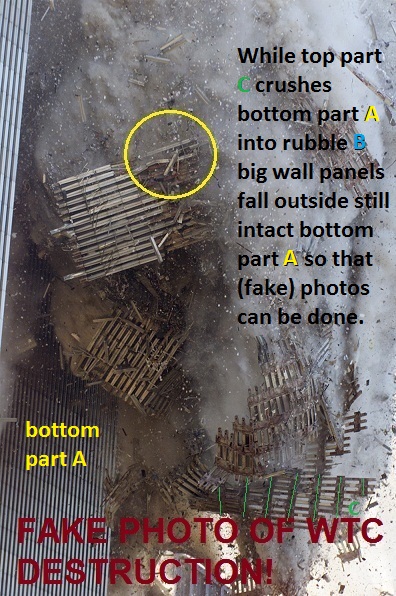
An image can only be considered, at best, as a virtual copy of reality. It cannot be used to prove the real-world occurrence of what it purports to depict. Any moviegoer knows that. Only a madman would contend that the 'Empire State building' (in fact, a digital depiction thereof) seen exploding and collapsing top-down in the 1996 movie "Independence Day" PROVES that it was actually destroyed in reality… On 9/11, we were shown two skyscrapers collapsing on TV in almost identical fashion (top-down). As it is, none of the extant and wildly contradictory images depicting these two physically inexplicable collapses proves that the event occurred as shown. Au contraire: its inconsistent, artificial and non-physical aspects strongly support the thesis that what was shown on TV on 9/11 was nothing but a "Hollywood-style" production - from start to finish.
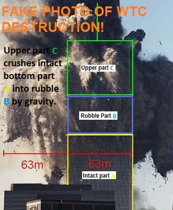
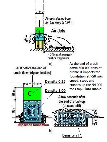
2.1 The false theory and the misleading assumptions An American professor Z P Bazant published, to support all above stupidly faked terrorist photos, soon after the WTC destructions 911 a theory supporting the terrorists (!) that was adopted by the authorities incl. the US government as true. The Bazant theory is that, if prolonged heating caused the majority of columns of a single top floor or top part C to lose their load carrying capacity, the whole, intact, solid, undamaged tower A below top part C is doomed. Part A goes Pouff, Pouff! Weak top part C crushes strong bottom part A. Everybody knows that no tower can ever collapse from top by gravity as described by Björkman. Bazant, a 100% US terrorist, 2001 ridiculously suggested the opposite, i.e. there are six stages how top C destroys bottom A from above and two stages when top C is destroyed from below as illustrated in Fig. 2.1.1 below from the Bazant scientific, peer reviewed paper:
Stage 2: At such temperatures, structural steel suffers a decrease of yield strength and exhibits significant viscoplastic deformation i.e., creep - an increase of deformation under sustained load! This leads to creep buckling of columns which consequently lose their load carrying capacity! It is of course correct that heat affects steel material properties as shown in 7.1 below but if it contributed to the local collapses of walls/core is not ascertained or even possible. No column from the initiation area that had lost its load carrying capacity and exhibited viscoplastic deformation was found in the rubble. The local temperatures were later established to temporarily and locally have been max 500° C and the loss of load carrying capacity is then not critical. So the assumption about loss of load carrying capacity and viscoplastic deformation is also is misleading. Why does Bazant make such stupid errors? Why does he support terrorism? And why doesn't FBI arrest him? Stage 3 (Crush-down from top downwards starts): Once more than half of the columns in the critical floor (floors 94-95 of WTC1) that is heated most suffer buckling, the weight of the upper part of the structure above this floor can no longer be supported, and so the upper part starts falling down onto the lower part below the critical floor (floor 95 of WTC1), gathering speed until it impacts the lower part (floor 94 of WTC1). At that moment, the upper part has acquired an enormous kinetic energy and a significant downward velocity. Note that upper part full of smoke is assumed intact and aligned with the structure below. As shown in 7.4 below the static compressive stresses in the supporting structure were less than 0.3 yield stress. If you remove uniformly half the supports evidently the supporting structure below will be stressed to 0.6 yield stress. So the assumption about the weight above not being supported by half of the columns is also misleading. And no buckling of any kind will occur at 0.6 yield stress compression! Evidently more than half of the columns were never heated at all to any critical level as seen on videos. The outer walls were only locally and temporarily affected by fire. Nevertheless, assuming that more than half of the columns are simultaneously affected by heat; do these columns actually bend, twist or crumple up? Why do they not only compress more, while transferring the load to adjacent columns that still have ability to carry it? Why would the part (mass) above the heat affected column actually gather speed? There is plenty of resistance! The columns are still connected at both ends. Why would the upper part and its mass impact the lower part? What is the kinetic energy of the mass above with a mean density of 0.18 tons/m3? Why is it enormous? In 7.4 below it is shown that the energy could not have exceed 340 kWh in WTC1 which corresponds to abt 40 kgs of diesel oil! It is not an enormous amount of energy and cannot possibly start crushing the whole tower below. So the assumption about enormous kinetic energy is also false.
What is the enormous vertical dynamic load of the upper part? What is the load capacity of the underlying, not heated part? It will be shown in 9.1 below that, if the underlying structure is regarded as a spring, it will only compress max 78 centimeters due to an instantaneous vertical solid impact! And then bounce back! This is logical! The impact speed is low and the kinetic energy compressing the structure is very low and the structure below behaves elastically and brakes the load applied and breaks the upper block. No structure can be crushed by a little top part of itself.
It is not clear why the alleged impact - an upper part with deformed columns below hitting a lower part with intact floors and columns - would cause the underlying floors to disconnect from the underlying columns? The floors are bolted to the columns. How can a column that has deformed previously above then deform a column below ... over the height of many floors? Why do not the columns above, if disconnected, simply punch a hole in the floors beside the column below and get entangled with the structure below and their spandrels? Stage 5 is very strange and not recorded on any video. So the assumption by terrorist Bazant about failure of an underlying multifloor segment is not obvious. Stage 6: The part of building lying beneath is then impacted again by an even larger mass falling with a greater velocity and the series of impacts and failures then proceeds all the way down. This sounds like magic! Are any further impacts seen on the videos? The upper part must then still be assumed intact and aligned with the structure below all the time. You need kinetic energy, KE, for global collapse and it can only be provided by an intact, rigid, uniform density upper block that remains intact, rigid, with uniform density during the whole destruction of the lower structure. The upper block is the only part that can provide KE during the alleged global collapse. The lower structure does not add any extra KE to the collapse or contribute to the collapse as assumed by Bazant - it is being destroyed (lack of strain energy according NIST). But the upper block is the weakest part of the whole skyscraper! Stage 7: Upper part is destroyed in a crush-up by rubble below! Stage 8: Rubble finally spreads out on ground. It will be shown in this article that all
assumptions and conclusions in stages 1-6 are false and that
the Bazant stages 7 and 8 are not possible.
To assume that the
upper
part is intact and
aligned with the structure below, during ... and
after ... complete destruction of the bottom part
is not serious. Actually,
the whole theory of Bazant is terrorist nonsense!
Bazant treats the WTC-tower
as a uniform line (!) that gets shorter when
impacted (LOL) by a bit of the same line (the top
of the building) from above by gravity. But the
line is not uniform! It is 100 times stronger at
the bottom than the top. The small top would just
bounce on the big bottom in a serious analysis.
Bazant is not serious! He supports the terrorists.
He is a criminal. And FBI does nothing. Strange
world. Back
to Summary! 3.1
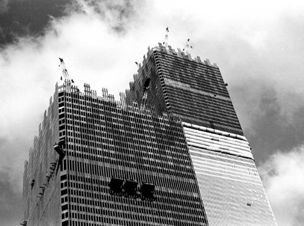
Introduction - a bird cage The structural design of the
World Trade Center Twin Towers was very
simple as its very lightweight steel framework is
similar to a box shaped bird cage in which human
beings are working. Most skyscrapers or office
towers in the world are built according similar
principles. None has ever globally collapsed in
seconds before or after 911 except WTC 1, 2 and
7. Fig. 3.1.1 - WTC under
construction
3.2 The bird cage wall bars and their spandrels - primary structure
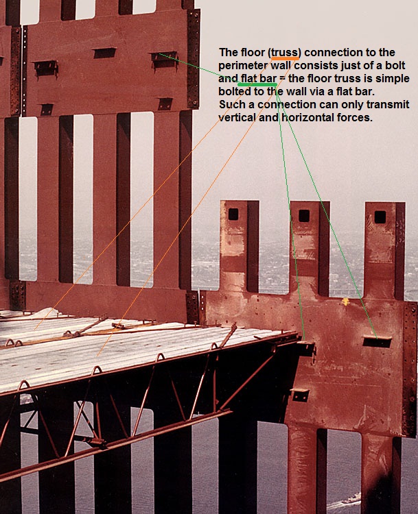
The wall columns are primary structure to carry the load imposed on them down to ground. Due to the spandrels the four walls are self-supporting. A wall columns assembly is about 11.1 m tall and 3 m wide and consists of three columns 1 m apart and three spandrels 3.7 m apart welded together as a prefabricated panel. The panels were then bolted together in the towers in a staggered fashion, i.e. column butt bolted connections, accessible through square holes in the columns, are at different levels - see fig. 3.3.1 and 4.1 - and the spandrels with 20 bolts + overlap plate.
3.3 The floors - secondary structure - panels bolted to the columns To better use the volume of the cage 110 off floors were installed in it at regular intervals. The WTC floors were also very simple.
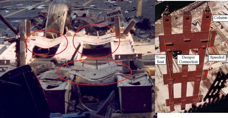
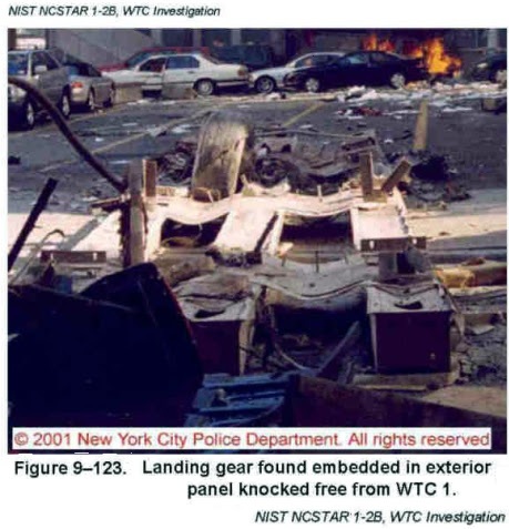
Fig. 3.3.4 The fake wall panel (left) compared to a real one right. You should really wonder why the perpetrators placed a fake wall panel in the WTC rubble. To confuse people? You will find descriptions of more fake rubble on the Letsrollforums.
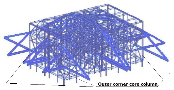
3.4 The core columns - more primary structure 47 off box or I-shaped columns were installed inside the cage at its core - core columns interconnected by horizontal beams. The floor trusses were bolted to the beams interconnecting the outer core columns. The core columns reduce the span of the floor trusses. Evidently the outer core columns carry more load than internal ones and most loads are carried by the outer corner core columns. See load distribution. A core column is similar to a wall column with dimensions tapered from bottom to top like a flag pole but are welded together. It only carries its own weight + the load on the floors connected to it. The core columns are interconnected with spandrel like solid, horizontal or sloping beams at regular intervals. The bracket connections column/beam are bolted/riveted. Evidently you fit elevator shafts, vertical cable/pipe/ventilation trunks and stairwells adjacent to the core columns. The core columns are also primary structure to carry the load imposed on them down to ground. The core structure is self-supporting (and cannot possibly self-destruct from top down by a local failure up top). During construction of the Towers the outer corner core columns and adjacent columns were used to support the four cranes used to lift all prefabricated outer wall and floor panels in position and bolt them together. The core columns are butt welded together at their ends and other bracket connections with horizontal or sloping beams are either riveted or welded.
3.5 The hat truss on WTC 1 On top of the cage a 'hat truss'
is fitted on WTC 1. It is 4 strong frames on each
side extending over three floors connecting four
core columns with four perimeter wall columns (not
shown) as per below figure: The main purpose of the hat
truss is to provide support for a TV mast on top of
the cage and distribute some loads to the wall
perimeter columns. As no mast was fitted on WTC2,
it is unlikely that WTC2 had a hat
truss. Fig. 3.5.1 - Hat
truss
3.6 The cage mass - volume wise most air It should be clear that 94-96% of the volume of the bird cage consists of air and that 100% of the cage mass/load is carried in the primary structure vertical columns down to ground. A column only carries its own weight + the load on the floors connected to it and the roof. At the bottom or ground level the columns thus carry the whole load of the column above and are tapered to smaller dimensions at the top only to carry the roof. The compressive stress due to weight (mass) of a column is therefore uniform from bottom to top and well below any critical stress (yield or buckling) that is shown below.
3.7 Redundancy - difference between primary and secondary structure The cage has very large redundancy, i.e. surplus strength due to the spandrels. You can remove a big number of primary structure columns or secondary structure floors at any location (e.g. a plane or other object crashes into the cage or a small bomb goes off and makes a hole in the cage!) and nothing happens, as the compressive load in the removed columns is transmitted via the spandrels to adjacent intact columns and down to the ground. It should be noted that primary structure is much stronger than secondary structure as secondary structure only carry it local loads to the primary structure that in turn carries all the loads of the secondary structure.
3.8 Total mass of the tower Information about the total mass of the Tower differs from 250 000 to 500 000 tons but is of little importance. The Towers were structurally sturdy and had survived many storms, etc. even if they then were subject to transverse deflections of several meters at the top. No structural defects were reported for 30+ years. The Towers also survived the initial impacts of planes on 911 due to their redundancy. When the Towers collapsed there were no storm wind forces acting on them. One reason why we do not know the mass of the Tower is that it appears the Towers were never completed! To build above structure was cheap. Big costs were then interior decorations, false ceilings, interior walls, floor coverings, outfitting of all types, furniture, etc, and it was to be done later when tenants were found. But no tenants were found and many floors, >50%, were left ... empty ... and years later they were used just for storage of paper. The Towers were white elephants in many respects.
3.9 Simplifications In order to study the collapse of the Tower cage structure it is easiest and most educational just to look at one of the wall columns and one of the core columns of the cage. The compressive load in these primary structure columns is the sum of the load from the bolted floor truss connection at every floor and the weight of the column itself above. Back to Summary!
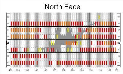
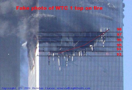
4.1 Collapse scenario and cause of collapse - buckled columns - lack of evidence From NIST report - NISTNCSTAR1-6D chapter 5.2 - we learn: "The aircraft impacted the north wall of WTC 1 at 8:46 a.m. … between Floor 93 and Floor 98. … The subsequent fires weakened structural subsystems, including the core columns, floors and exterior walls. The core displaced downward … At 100 min (at 10:28:18), the north, east, and west walls at Floor 98 carried 7 percent, 35 percent and 30 percent more gravity load loads … and the south wall and the core carried about 7 percent and 20 percent less loads, respectively., … At 10.28 a.m., 102 min after the aircraft impact, WTC1 began to collapse. … The release of potential energy due to downward movement of the building mass above the buckled columns exceeded the strain energy that could be absorbed by the structure. Global collapse ensued." From chapter 5.3 we learn: "The aircraft … impacted the south wall of WTC 2 at 9.03 a.m. … between Floor 78 and Floor 84. … (9:59 am) … The release of potential energy due to downward movement of the building mass above the buckled columns exceeded the strain energy that could be absorbed by the structure. Global collapse ensued." The 9.03 a.m. impact was filmed by many people. All such "amateur" videos are fakes using CGI, e.g. this one where the plane comes in low and WTC 2 is impacted higher up. The mass of each aircrafts was about 150 000 kgs and the impact velocities were estimated at 211 m/s and 265 m/s. So at impacts about 3.34 GJ and 5.27 GJ energies were applied and caused some local failures to the Towers and shredded the aircrafts. Note that the two Towers later collapsed for exactly the same cause: The release of potential energy, PE, due to downward movement of the building mass above the buckled columns exceeded the strain energy, SE, that could be absorbed by the structure. Note that NIST does not mention that top of structure dropped (release of potential energy due to downward movement?) and 'impacted' the bottom of structure - a collision - when strain energy is of interest. NIST's explanation why the strong bottom structure, which statically carried the weak top structure for 30 years, suddenly just failed, floor by floor is nonsense. "Buckled" of steel structure by definition means bent, twisted or crumpled up and is the key word of the NIST announced only cause/effect of the global collapse.
4.2 The buckled columns It is suggested in NIST report - NISTNCSTAR1-6D that all the wall and core primary structure columns suddenly buckled simultaneously in the impact area as they were affected by fire/heat 40-100 minutes later that reduced their strength (yield stress) and caused subsequent overloading. Even if this phenomenon is not seen on any video of the collapse itself - instant forensic analysis - or in the columns of the rubble afterward - post mortem forensic analysis -, let's assume that all our vertical cage bars or columns buckled due to heat of the fire. Another possibility is that the wall columns simply shears off at their bolted connections between columns. Buckling of the cage bar or column occurs, when the compressive stress in the bar exceeds the critical buckling or collapse stress of the bar. The critical buckling stress is only a function of the slenderness ratio of the bar, its cross area and material properties. Only the material properties are affected by the heat but are virtually unchanged between 20 and 500° C but let's assume that, e.g. the yield stress is reduced by 20% (from say 248 to 200 MPa) at 500°C. The wall bar is obviously fitted in the wall and cooled by external air and can never be heated very much. That is why the wall perimeter steel columns were not fire proofed but only fitted with normal heat insulation against sun and winter weather below an external aluminium cladding. When the wall bar buckles, it will deflect sideways which however is prevented by both the spandrels and the floors, i.e. it can only buckle between these supports. Both spandrels and floors keep our primary structure wall bar in vertical position as long as they are intact. If the secondary structure floor bolted connections are sheared off and the unsupported length of the bar between floors increases, the spandrels will still restrain outward or inward deflection of our bar due to buckling. Same applies to a primary structure core column.
4.3 Release of potential energy due to downward movement Downward movement/displacement of the mass above, i.e. the columns' weight and the load of the floors attached to them are only possible due to transverse deflection (bending) or vertical crumpling up of the columns. If the column does not deflect or crumple up, there is no downward movement of the mass above and thus no release of potential energy. And definitely not an 'impact'. Back to Summary!
5.1 Arrangements at floors 94-98 of WTC 1 Let's look at WTC1 and floors 94-98 - the initiation zone. Total area of each floor is about 4 000 m². A wall bar or column there is a box with side 300 mm and wall thickness, say 12.5 mm. The cross area of the steel is thus about 150 cm². The bar weighs about 120 kgs/m incl. spandrels, i.e. is quite light. There are about 236 wall columns. Total cross area of all wall columns is then 3.54 m² Let's assume that the total mass of the wall steel columns above floors 94-98 is about 1 500 tons. The highest loaded core columns are the outer ones, e.g. number 501. It is an H-beam with two flanges 17x3.5 inch connected by a 2.2x12.6 inch web. In metric terms the cross area is about 950 cm², i.e. the bar is very solid. It weighs 750 kgs/m. There are 47 core columns most of them with less cross area than the outer ones. Let's assume that total cross area of all core columns is only 2.1 m², i.e. 60% of the wall columns. Then the total mass of the core columns and spandrels above floors 94-98 is about 900 tons. The core is thus lighter than the perimeter wall. A floor including furniture, etc is assumed to weigh about 1 850 tons. The total mass of floors and the roof above floors 94-98 is about 26 000 tons. Most of this weight is in fact concrete poured on a thin corrugated steel plate supported by trusses that in turn are bolted to the columns - 3.3. There are about 500 connecting bolts per floor. Let's summarize the total mass above as follows:
5.2 Total mass above floors 94-98 - 33 000 tons Steel wall columns 1 500 tons Steel core columns 0 900
tons Steel floor trusses 3 000 tons Concrete floors 23 000 tons Windows and misc. 4 600 tons Total 33 000 tons Note in table left that less
than 8% of the mass is steel in the supporting
primary structure columns and that as much as 70%
is concrete. If this mass filled the total volume
of the building above the initiation zone (190 000
m3), the uniform density would be 0.18
ton/m3 or the density of cotton! You
could say that a big bale of cotton (mass above)
rested on the structure below! This mass
is carried about 50/50 by walls and
core. Note: Other sources suggest that the total mass above floors 94-98 was 39 000 or even 54 000 tons, but it does not change the conclusions below. The stresses will be 18% or 63% bigger as suggested by this author but still well below any critical stress.
5.3 Compressive stresses in the primary structure columns - less than 1/3 of the yield stress The mass above the walls at floors 94-98 is thus about 16 500 tons supported by 236 wall columns (total cross area 3.54 m²). Therefore each wall column on average supports 70 tons. The compressive stress in the wall column at floors 94-98 with cross area 150 cm² is thus abt 467 kgs/cm² or 46 MPa or 18.8% of the yield stress (abt 248 MPa) of the steel. When the North wall is damaged the stresses in the East and West wall columns may increase 20% or to abt 560 kgs/cm² or 55 MPa or 22.2% of the yield stress NIST suggests that the static loads will be increased further 35% in the East wall and 30% in the West wall (all 100% intact) due to load transfers just prior collapse, i.e. the compressive stresses in columns there becomes 74.2 and 71.5 MPa, which is still only 30% and 29% if the yield stress. Actually these are the increased stresses you would expect due to wind under hurricane conditions. The mass above the core is also 16 500 tons supported by the 47 core columns with total area 2.1 m². On average each core column carries abt 351 tons so the average compression is 786 kgs/cm² or 78 MPa or 31.7% of yield. The outer core columns carry more mass and the outer corner core columns the most load, e.g. no. 501 with cross area 950 cm². It may carry as much as 750 tons. The compressive stress in the no. 501 core column at floors 94-98 is thus abt 789 kgs/cm² or 78 MPa or 31.7% of the yield stress of the steel. It is assumed that the compressive stress in the other core columns is abt the same or less. NIST suggests that the load in the core is reduced 20% just prior collapse, i.e. the stresses are reduced. However, some core columns may have been damaged in the initiation zone, so in all probability the stresses in the remaining columns may have remained at 30% yield stress. The reason why original the static stresses are higher in the core than in the perimeter walls is that the wall columns are also designed to absorb dynamic wind loads. Back to Summary!
6.1 The towers were built very strong in the 1960's The above is a clear indication how the Towers were originally built by serious architects and engineers in the 1960's. Compressive static stresses in the primary structure columns were less than 1/3 of the yield stress of the steel before (obviously) ... and after serious damage (not so obvious but shown here)! The buckling stress of the column is virtually the same as the yield stress as the columns were arranged with spandrels. One reason why the static stresses were so low was that the designers had no access to computers to optimize (slender down) the construction. Manual calculations were done and to be on the safe side you added steel and built strong! And steel was quite cheap at that time. And US steel was good quality. The assumed yield stress 248 MPa was probably much higher in reality. NIST never checked the yield stress of the steel from the initiation zone in the rubble! They only sampled some other steel. There was therefore plenty redundancy. A plane may crash into the bird cage and destroy columns and floors and nothing else really happens, e.g. global collapse. A big fire may break out and nothing happens. Why? Because the normal compressive stress in the supporting vertical structure is so low and if any column breaks or buckles, its load is transmitted to adjacent columns via the spandrels and the stress in adjacent columns increase a little. No global collapse is possible under any circumstances. Evidently the columns got stronger (thicker plates, steel with higher yield stress) further down when the 'mass above' increases, but it is certain that the compressive stresses in the Towers never exceed 1/3 of the yield stress. Same applies for the buckling stresses. Back to Summary!
Go to Part 7.1 that is very interesting with videos that clearly show what happens before downward motion starts, etc.
|